Florida Institute of Technology
PHY 2092
Experiment 10 Magnetic Induction Introduction . This is a four-part experiment. Parts 1 and 2 contain several demonstrations and questions on Lorentz's and Faraday’s Laws. In Part 3 you use an oscilloscope to measure the time constant of an RL Circuit very similarly to part of the RC Circuit experiment. In Part 4 you construct an LC
...[Show More]
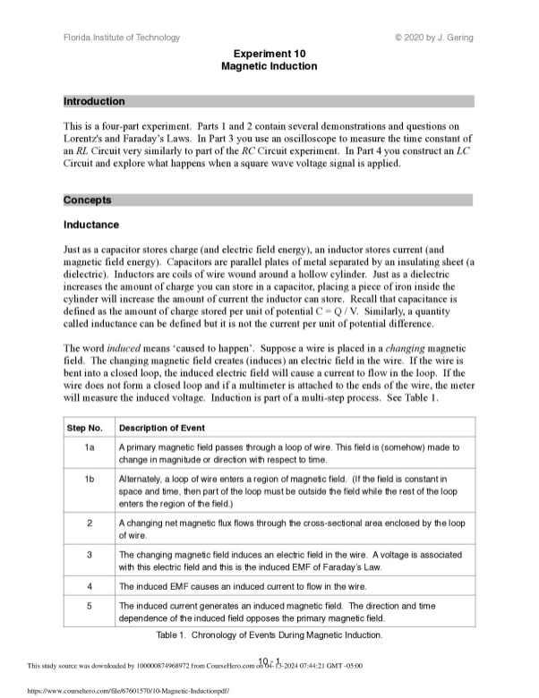
Experiment 10 Magnetic Induction Introduction . This is a four-part experiment. Parts 1 and 2 contain several demonstrations and questions on Lorentz's and Faraday’s Laws. In Part 3 you use an oscilloscope to measure the time constant of an RL Circuit very similarly to part of the RC Circuit experiment. In Part 4 you construct an LC Circuit and explore what happens when a square wave voltage signal is applied. Concepts . Inductance Just as a capacitor stores charge (and electric field energy), an inductor stores current (and magnetic field energy). Capacitors are parallel plates of metal separated by an insulating sheet (a dielectric). Inductors are coils of wire wound around a hollow cylinder. Just as a dielectric increases the amount of charge you can store in a capacitor, placing a piece of iron inside the cylinder will increase the amount of current the inductor can store. Recall that capacitance is defined as the amount of charge stored per unit of potential C = Q / V. Similarly, a quantity called inductance can be defined but it is not the current per unit of potential difference. The word induced means ‘caused to happen’. Suppose a wire is placed in a changing magnetic field. The changing magnetic field creates (induces) an electric field in the wire. If the wire is bent into a closed loop, the induced electric field will cause a current to flow in the loop. If the wire does not form a closed loop and if a multimeter is attached to the ends of the wire, the meter will measure the induced voltage. Induction is part of a multi-step process. See Table 1. Table 1. Chronology of Events During Magnetic Induction. Step No. Description of Event 1a A primary magnetic field passes through a loop of wire. This field is (somehow) made to change in magnitude or direction with respect to time. 1b Alternately, a loop of wire enters a region of magnetic field. (If the field is constant in space and time, then part of the loop must be outside the field while the rest of the loop enters the region of the field.) 2 A changing net magnetic flux flows through the cross-sectional area enclosed by the loop of wire. 3 The changing magnetic field induces an electric field in the wire. A voltage is associated with this electric field and this is the induced EMF of Faraday’s Law. 4 The induced EMF causes an induced current to flow in the wire. 5 The induced current generates an induced magnetic field. The direction and time dependence of the induced field opposes the primary magnetic field. 10 - 1 This study source was downloaded by 100000874968972 from CourseHero.com on 04-13-2024 07:44:21 GMT -05:00 https://www.coursehero.com/file/67601570/10-Magnetic-Inductionpdf/ Florida Institute of Technology © 2020 by J. Gering (1) Faraday’s Law, General Form Faraday’s Law, for a Single Solenoid (Lenz’s Law is taken to be the minus sign) Inductance is the proportionality constant between cause and effect for this induction phenomenon. The cause is the changing current I(t), which creates the changing (primary) magnetic field B(t) mentioned in Table 1. The effect is the induced voltage in a wire loop. Hence the units of inductance are [
[Show Less]