Discussion Question 7AP212, Week 7RC CircuitsThe circuit shown initially has the capacitor uncharged, and the switch connected to neitherterminal. At time t = 0, the switch is thrown to position a.E = 12 VC = 5 PFR1 = 3 :R2 = 6 :R2E R1Cab(a) At t = 0+, immediately after the switch is thrown to position a, what are the currents I1and I2 across the two resistors?What does the uncharged capacitor loo
...[Show More]
Discussion Question 7A
P212, Week 7
RC Circuits
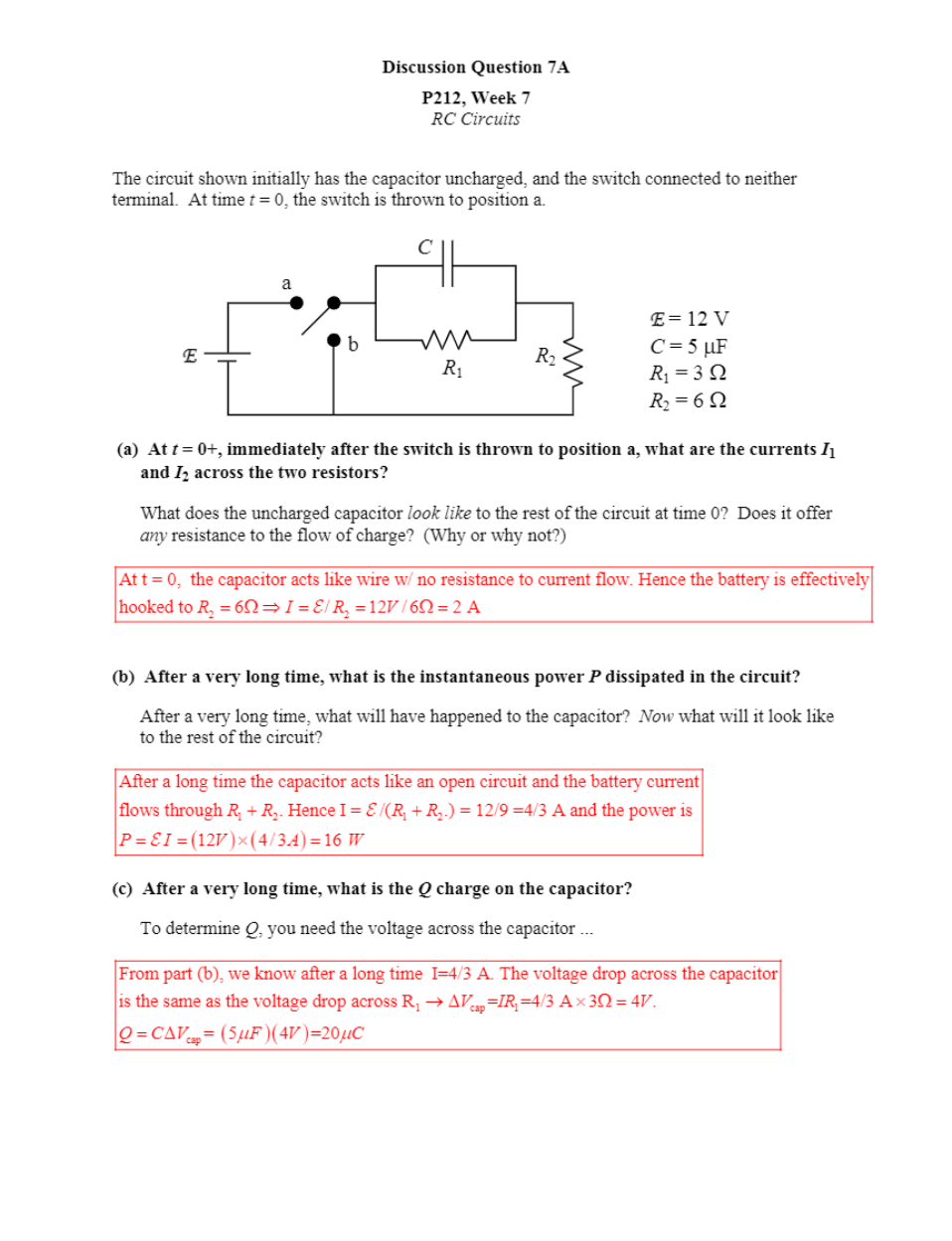
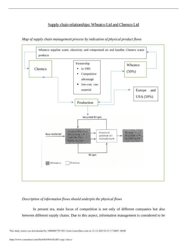
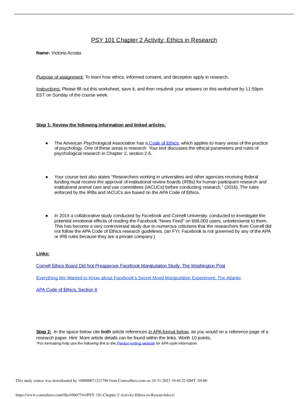
The circuit shown initially has the capacitor uncharged, and the switch connected to neither
terminal. At time t = 0, the switch is thrown to position a.
E = 12 V
C = 5 PF
R1 = 3 :
R2 = 6 :
R2
E R1
C
a
b
(a) At t = 0+, immediately after the switch is thrown to position a, what are the currents I1
and I2 across the two resistors?
What does the uncharged capacitor look like to the rest of the circuit at time 0? Does it offer
any resistance to the flow of charge? (Why or why not?)
2 2
At t = 0, the capacitor acts like wire w/ no resistance to current flow. Hence the battery is effectively
hooked to 6 / 12 / 6 2 A R I R V : : �
(b) After a very long time, what is the instantaneous power P dissipated in the circuit?
After a very long time, what will have happened to the capacitor? Now what will it look like
to the rest of the circuit?
1 2 1 2
After a long time the capacitor acts like an open circuit and the battery current
flows through . Hence I = /( .) = 12/9 =4/3 A and the power is
12 4/3 16
� �
u
R R R R
P I V A W
�
�
(c) After a very long time, what is the Q charge on the capacitor?
To determine Q, you need the voltage across the capacitor ...
1 cap 1
cap
From part (b), we know after a long time I=4/3 A. The voltage drop across the capacitor
is the same as the voltage drop across R = =4/3 A 3 4 .
= 5 4 =20 P P
o ' u :
'
V IR V
Q C V F V C
[Show Less]