NAME STUDENT IDMonish Mohit Chand S11170591Folauhola Toumoua S11143270Aditiya Jeet S11175234AIM• learn the usage of basic electronics lab equipment, and• do simple circuit analysis using the Circuit Maker software.THEORYThe unit aims to provide students with a sound knowledge of electrical circuits, circuitanalysis techniques, transformers, motors, generators as well as digital electronic circ
...[Show More]
NAME STUDENT ID
Monish Mohit Chand S11170591
Folauhola Toumoua S11143270
Aditiya Jeet S11175234
AIM
• learn the usage of basic electronics lab equipment, and
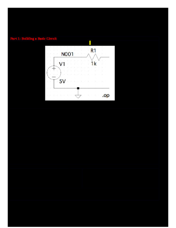
• do simple circuit analysis using the Circuit Maker software.
THEORY
The unit aims to provide students with a sound knowledge of electrical circuits, circuit
analysis techniques, transformers, motors, generators as well as digital electronic circuits.
Electrical circuits begins with a revision of basic fundamentals including Direct-Current
(DC) circuits. The concept of nodal-analysis (node-voltage method) for the analysis of DC
circuits is introduced. The principle of Superposition, derivation of There in and Norton
equivalent circuits are discussed in detail as well as the maximum power transfer theorem.
Alternating-Current (AC) circuits are explored and the analysis of these circuits using
complex numbers is covered. Three-phase AC systems are studied and the concept of
power factor correction is introduced. An overview of electrical transformers is given.
Finally, DC and AC motors are examined as well as synchronous generators. Digital
Electronics begins with a discussion of arithmetic operations, Boolean expressions and
their reduction techniques.
INSTRUMENTS
• All equipment mounted on a typical electronics workbench such as power supply,
oscilloscope, signal generator, and multimeter
• 3 × Randomly selected resistors
• BNC to BNC cables
• PC installed with Circuit Maker
METHODOLOGY
Part I – Reading Resistor Values
The lab group was required to determine the resistance of the three random resistors given
using the resistor color coding system (also available on Moodle). Next the multimeter was
used to measure the resistance and all the results were noted down in Table 8.1. Also, the
percentage error between the measured and calculated values were calculated.
Part II – Power Supply Basics
Using the digital power supply, the DC voltages at increments of 2.5V from 0 – 30V were
generated. The meter on the power supply was used for this. At each increment, the voltage
was measured using the multimeter. The results were noted in Table 8.2.
[Show Less]


-preview.png)