Sabriya Zaynab SilvaBME 2210-B16Monday, December 5, 2016[Type here]Sabriya Zaynab Silva BME 2210-B16 | Lab Report 3:Amplifiers2PART 1. Voltage FollowerQuestions:a. Find in the online datasheet the following typical (TYP) values for the MCP6002amplifier: Input offset voltage (VOS), input bias current (IB), input offset current (IOS).What are the MCP6002 amplifier values for these three, and what
...[Show More]
Sabriya Zaynab Silva
BME 2210-B16
Monday, December 5, 2016
[Type here]
Sabriya Zaynab Silva
BME 2210-B16 | Lab Report 3:
Amplifiers2
PART 1. Voltage Follower
Questions:
a. Find in the online datasheet the following typical (TYP) values for the MCP6002
amplifier: Input offset voltage (VOS), input bias current (IB), input offset current (IOS).
What are the MCP6002 amplifier values for these three, and what would ideal op-amp
assumptions be for each?
[Type here]
Sabriya Zaynab Silva
BME 2210-B16 | Lab Report 3:
Amplifiers3
Input offset voltage (VOS): -4.5 mV – 4.5 mV
Input bias current (IB): ±1.0 pA
Input offset current (IOS): ± 1.0 pA
The ideal op-amp assumption is where all the above is equal to 0.
b. The maximum current that can be delivered from the output is the “short-circuit output
current” (ISC); what is this value for the MCP6002 at a supply of about 5V?
Short-circuit output current” (ISC): ± 23 mA
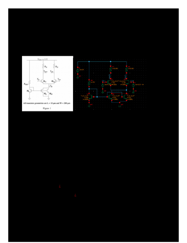
c. In the circuit shown in Fig. 1.3, compare the circuit diagram on the left and the Arduino
wiring pattern on the right. For each lettered node in the circuit (A-D), what is the color
of the corresponding wire connection to the Arduino?
A: red
B: yellow
C: black
D: blue
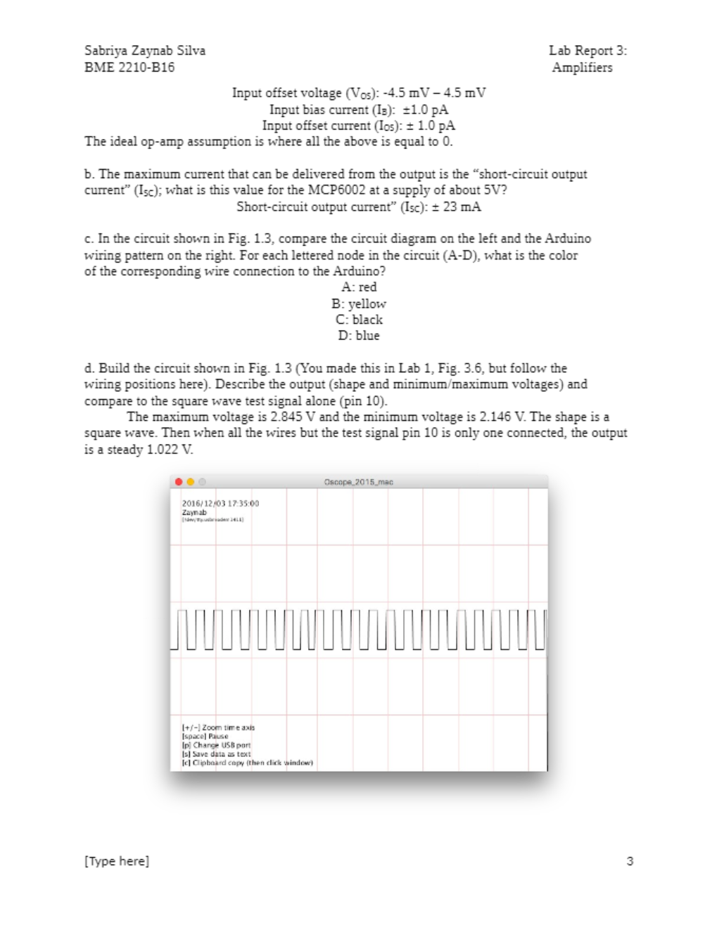
d. Build the circuit shown in Fig. 1.3 (You made this in Lab 1, Fig. 3.6, but follow the
wiring positions here). Describe the output (shape and minimum/maximum voltages) and
compare to the square wave test signal alone (pin 10).
The maximum voltage is 2.845 V and the minimum voltage is 2.146 V. The shape is a
square wave. Then when all the wires but the test signal pin 10 is only one connected, the output
is a steady
[Show Less]


-preview.png)