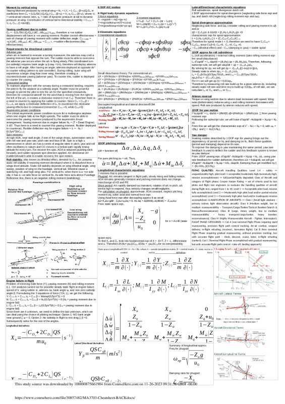
Moment by vertical wing
Yawing Moment produced by vertical wing = Nv = lvYv = lv Cl`α`v (β+σ)QvSv, in
coefficient form CN = (lvSv/Sb) (Qv/Qw) Cl`α`v (β+σ) = Vv ηv Cl`α`v (β+σ), where Vv
= vertical tail volume ratio, ηv = ratio of dynamic pressure at tail to dynamic
pressure at wing. Contribution of vertical tail to directional stability = CN`β`v =
Vv ηv Cl`α`v (1+dσ/dβ).
Yawing coefficient due to rudder
CN = - (lvSv/Sb) (Qv/Qw) (dCL`v/dδrudder) δrudder, therefore a +ve rudder
displacement will have a –ve yawing moment. Rudder control effectiveness =
rate of change of yawing moment with rudder deflection angle. CN`δ`rudder =
-ηvVv(dCL`v/dδrudder), dCL`v/dδrudder = CL`α`v τ, τ=rudder effectiveness (flap
effectiveness).
Requirements for directional control
Adverse yaw
when a/c is banked to execute a turning maneuver, the ailerons may cre8 a
yawing moment that oppose the turn. The rudder must be able to overcome
the adverse yaw occurs when the a/c is flying slowly. Pilot coordinated turn
(no sideslip) requires bank angle φ (cosφ =1/n), therefore will deploy ailerons
to have a roll angle. After having an angle, ailerons deployed at opposite dirn
to counter rolling (aileron is rate controller). During rolling, outer wing will
experience a larger drag than inner wing, therefore creating a
counterclockwise yawing (adverse yaw). To counter this, rudder is deployed
to counter the yawing.
Crosswind landing
To maintain alignment with the runway during a crosswind landing, requires
the pilot to fly the airplane at a sideslip angle. Rudder must be powerful
enough to permit the pilot to trim the a/c for the specified crosswinds.
Direction for crosswind takeoff: for the wind that is moving from the right to
the left of the a/c, it creates a clockwise moment (+ve CN). Therefore there is
a need to counter by applying the rudder to counter. Since CN = CN`ββ +
CN`δ`rδr, we apply a clockwise deflection of δr, to counteract the clockwise
yawing effects due to crosswind (remember CN`δ`r <0, while CN`β<0)
Asymmetric power conditions
The critical asymmetric power condition occurs for a multiengine airplane
when one engine fails at low flight speeds. The rudder must be able to
overcome the yawing moment produced by the asymmetric thrust
arrangement. Yawing moment due to engine failure NE = (T + Dead Engine)
X d/2. Thus there is a need to counter this yawing moment. Rudder deployed
to counteract. Rudder deflection req for engine failure = δr = - NE /
(0.5ρV2SbCN`δ`r)
Spin recovery
At high AOA, near stall angle, if one of the wings drops, autorotation sets in
with roll rate and yaw rate, pitch rate and loss of lift. Spin is a high α
phenomenon in which a/c has a combi of angular rates in pitch, yaw and roll
often oscillatory in nature and CG moves in a helical path rapidly losing
altitude for every turn. For recover frm spin, AOA is reduced (pushing stick
forward), and rudder opposite spin direction applied. A/c directional ctrl
(rudder)should b able to enable recovery frm spin motion.
Roll stability, also known as dihedral effect, denoted by Cl`β. A/c possess
static roll stability if restoring moment developed when it is disturbed from a
wings-level attitude. Static roll stability depends on wing dihedral angle, wing
sweep, position of wing on the fuselage, vertical tail. Dihedral cause a
stabilizing roll, and high wing also. For vertical fin, when there is a +ve side
slip, it has a –ve side force on vertical fin. As side force acts above Fuselage
Reference line, there is an negative rolling moment (stabilizing).
Engine failure in flight
Problem of trimming Side force (Y), yawing moment (N) and rolling moment
(L). Ctrl analysis carried out for possible steady state flight at engine failure
speed of V, using rudder δr, ailerons δa, bank angle φ, and non-zero sideslip
angle β. Formulating the 3 equations of force (Y,N, L), we get the following.
Y: CY`δ`r δr + CY`δ`a δa + CY`β β + Wsinφ/(0.5ρV2S) = 0
N: CN`δ`r δr + CN`δ`a δa + CN`β β + NE/(0.5ρV2Sb) = 0 (NE = yawing moment due to
engine fail)
L: Cl`δ`r δr + Cl`δ`a δa + Cl`β β + LE/(0.5ρV2Sb) = 0 (LE = yawing moment due to
engine fail)
Since there are 4 unknown, we need to define the last unknown, which we
can deal using the choice of piloting technique: Option 1: NO bank angle
near ground φ = 0, Option 2: No sideslip in flight to min drag β =0.
Subsequently solve for the rest of the angles.
6 DOF A/C motion
6 Rigid body dynamic equations
3 force equations
X –mgsinθ = m(ů+qw-rv)
Y+mgcosθsinφ=m( +ru-pw) Ṽ
Z+mgcosθcosφ=m( +pv-qu) ẇ
6 Kinematic equations
3 translational equations
(´ x ´ y ´ zi ii)=[cθcψ cθsψ −sθ −c cψ c sψ ϕϕ s cθ +ϕ+s sθsψ s sθsψ ϕϕ −s sψ s cψ ϕϕ c cθ +ϕ+c sθcψ ϕ c sθsψ ϕ ](wu v )u=v v= =w=0 0 0
Small disturbance theory: For conventional a/c
∆X = (∂X/∂u)∆u + (∂X/∂w)∆w +(∂X/∂δelevator)∆δelevator +(∂X/∂δThrottle)∆δThrottle
∆Y = (∂Y/∂v)∆v + (∂Y/∂p)∆p + (∂Y/∂r)∆r +(∂Y/∂δrudder)∆ δrudder
∆Z = (∂Z/∂u)∆u + (∂Z/∂w)∆w + (∂X/∂ ) ẇ ∆ẇ + (∂Z/∂q)∆q +(∂X/∂δelevator)∆δelevator +
(∂X/∂ δThrottle)∆δThrottle
∆L = (∂L/∂v)∆u + (∂L/∂p)∆p + (∂L/∂r)∆r +(∂X/∂δrudder)∆δrudder +(∂X/∂aileron)∆δaileron
∆M = (∂M/∂u)∆u + (∂M/∂w)∆w + (∂M/∂ ) ẇ ∆ẇ + (∂M/∂q)∆q +(∂M/∂δelevator)∆δelevator +
(∂X/∂ δThrottle)∆δThrottle
∆N= (∂N/∂v)∆v + (∂N/∂p)∆p + (∂N/∂r)∆r +(∂N/∂δrudder)∆δrudder +(∂N/∂ δaileron)∆δaileron
Decoupled longitudinal and lateral direction/EOM
Longitudinal
Lateral
State space Longitudinal EOM: ẋ = Ax + Bu, where A = aerody/propulsion matrix, B = control matrix, X = state vector, u
= control vector definition: force:
X
(∙)=
1m
∂ X
∂(∙) ;Y (∙)=m1 ∂∂(Y∙) ;Z(∙)=m1 ∂∂(Z∙) ;
L
(∙)=
1I
xx
∂ L
∂(∙) ; M(∙)=I1yy ∂∂(M∙) ; L(∙)= I1zz ∂∂(N∙) ;
(∆∆ ∆ ∆ wu q θ´ ´ ´ ´ )=[M u1+−XZ1 0Mu Zu−w w´´ZZw´u M w1+−XZ0M 1w Zw−w w´´ ZZww ´ Mq+ Z 1 M−q0 w 1+ 1´ Z(−uZw´0q Z+w´ u0 ) −−−M1 1ggw´− −cos sin g 0Z Zsin w w´ ´θθ00θ0](∆∆ ∆ ∆ wu q θ )+[M
1DOF pitching motion
∆M = function of(
∆ α , ∆ a´ , ∆ q , ∆ δe )
For pure pitching ∆α = ∆θ, Thus,
α´ =M
α ∆ α+(Mα+Mq)∆ α´ +Mδe ∆ δe .
Longitudinal characteristic equations
2 motions that is possible:
Phugoid: A/c remains tangent to flight path, slowly rising and falling motion.
AOA remains generally constant and pitching moment does not change.
Interchange of KE and PE
Short period: A/c rapidly damped out transient, rotation of a/c in pitch. a/c
inertia high to respond, thus velocity changes small/negligible.
For calculation on phugoid, approximate: AOA constant, neglect pitching
moment eq, solve axial and normal force eqn.
Using Axial force eqn after decoupling approx θ as small
∆ů=Xu∆u-g∆θ ; Zu∆u+u0∆q = 0. As ∆q = ∆(dθ/dt), ∆(dθ/dt) = -Zuu0/∆u
From state space eqn,
x=(Δu Δθ), A=(−X uZ0uu −0g) for = Ax+B (state ẋ
space eqn).
To find Xu and Zu, look into fundamental eqn of X = -D+T, Z = -L, differentiate
wrxt u. Therefore ∂X/∂u=-ρu0SCD0, ∂Z/∂u = -ρu0SCL0 for no compressibility
Lateral/Directional characteristic equations
Roll subsidence, spiral divergence dutch roll.
2 DOF approximation for spiral divergence (neglecting side force eqn and
∆φ, and dutch roll (neglecting rolling moment eqn and ∆φ).
Spiral divergence approximation
Neglecting side force and ∆φ, consider rolling and yawing moment in ∆β
and ∆r
∆β = (Lr/Lβ)∆r & d∆r/dt + [(LrNβ-LβNr)/Lβ]∆r =0
characteristic eqn for spiral approximation
λ = (LrNβ-LβNr)/Lβ λ = (CLrCNβ-CLβCNr)/CL`β.
Therefore for spiral mode λ < 0, therefore we need to have CLrCNβ <
CLβCNr, since CLβ<0, CNr<0, CLr >0, CNβ >0.
↑ CLβ (dihedral effect) and ↑ CNr (damping in yaw) = stable spiral
1DOF approx for roll subsidence
Ixx (roll acceleration) = external rolling moment (take rolling moment eqn
frm small disturbance)
Ixx d2∆φ/dt2 = Ixx d∆p/dt = (∂L/∂p) ∆p + (∂L/∂δa)∆δa. Therefore, following
subscript rule, we will get τd∆p/dt + ∆p = -(Lδ`a/Lp)∆δa.
By solving for ∆p, we will get ∆p = -(Lδ`a/Lp)[1-exp(-t/τ)]∆δa
Steady state is when ∆pss = -(Lδ`a/Lp) ∆δa,
Lp = Cl`p(b/2u0)(0.5ρu02Sb)/Ixx and Lδa = Cl`δ`a(0.5ρu02Sb)/Ixx
∆pssb/2u0 = -(Cl`δ`a/Cl`p)∆δa
For t=τ we will get ∆p (t) = 0.63∆pss
Therefore by measuring roll rate build up for a given aileron i/p, including
steady state roll rate and time req to build up 0.63pss of roll rate, we can
calculate Lp or Cl`p and Lδ`a or Cl`δ`a
Aileron reversal
Torque on wing section due to aileron load increases with speed. Wing
twist (deformation) reduces wing α and rolling moment decreases with
speed. Roll rate produced by aileron reduces with speed.
1DOF for yaw motion
Izzd2∆ψ/dt2 = Izz d∆r/dt = (∂N/∂β) ∆β+(∂N/∂r)∆r + (∂N/∂δr)∆δr from yawing
moment eqn
Following the subscript rule, we will have d2∆ψ/dt2 –Nrd∆ψ/dt + Nβ∆ψ = Nδ`
-preview.png)
-preview.png)