New York University ECE-GY 6473 ECE 6473 Midterm Test sol. - ECE 6473 Midterm Test Monday November 11th 2019 Maximum Time: 2 ½ hours: 9:50 AM – 12:20 PM Calculators 2-sided Cheat
Monday November 11th 2019
Maximum Time: 2 ½ hours: 9:50 AM – 12:20 PM
Calculators, 2-sided Cheat sheet allowed. Devices with internet connectivity not permitted. Please answer
all questions. Please show all
...[Show More]
New York University ECE-GY 6473 ECE 6473 Midterm Test sol. - ECE 6473 Midterm Test Monday November 11th 2019 Maximum Time: 2 ½ hours: 9:50 AM – 12:20 PM Calculators 2-sided Cheat
Monday November 11th 2019
Maximum Time: 2 ½ hours: 9:50 AM – 12:20 PM
Calculators, 2-sided Cheat sheet allowed. Devices with internet connectivity not permitted. Please answer
all questions. Please show all work.
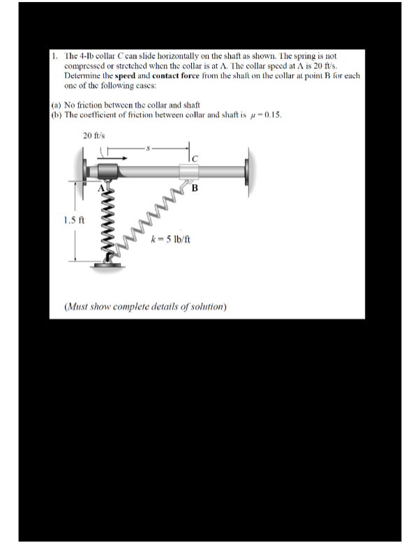
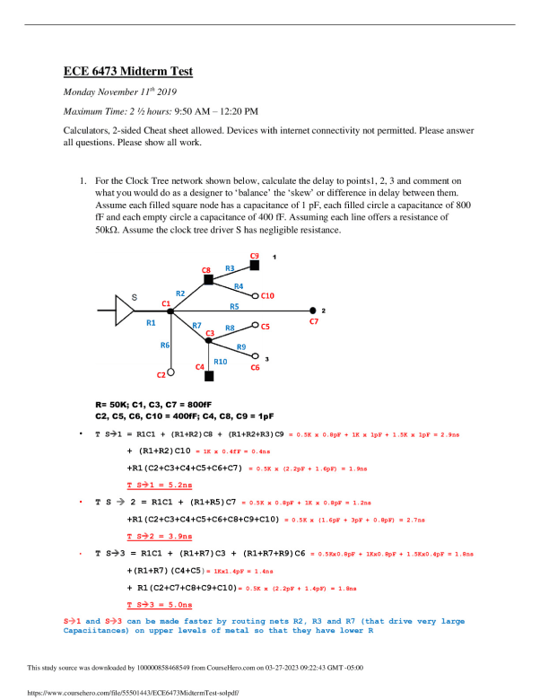
1. For the Clock Tree network shown below, calculate the delay to points1, 2, 3 and comment on
what you would do as a designer to ‘balance’ the ‘skew’ or difference in delay between them.
Assume each filled square node has a capacitance of 1 pF, each filled circle a capacitance of 800
fF and each empty circle a capacitance of 400 fF. Assuming each line offers a resistance of
50k Assume the clock tree driver S has negligible resistance.
R= 50K; C1, C3, C7 = 800fF
C2, C5, C6, C10 = 400fF; C4, C8, C9 = 1pF
• T S→1 = R1C1 + (R1+R2)C8 + (R1+R2+R3)C9 = 0.5K x 0.8pF + 1K x 1pF + 1.5K x 1pF = 2.9ns
+ (R1+R2)C10 = 1K x 0.4fF = 0.4ns
+R1(C2+C3+C4+C5+C6+C7) = 0.5K x (2.2pF + 1.6pF) = 1.9ns
T S→1 = 5.2ns
• T S → 2 = R1C1 + (R1+R5)C7 = 0.5K x 0.8pF + 1K x 0.8pF = 1.2ns
+R1(C2+C3+C4+C5+C6+C8+C9+C10) = 0.5K x (1.6pF + 3pF + 0.8pF) = 2.7ns
T S→2 = 3.9ns
• T S→3 = R1C1 + (R1+R7)C3 + (R1+R7+R9)C6 = 0.5Kx0.8pF + 1Kx0.8pF + 1.5Kx0.4pF = 1.8ns
+(R1+R7)(C4+C5)= 1Kx1.4pF = 1.4ns
+ R1(C2+C7+C8+C9+C10)= 0.5K x (2.2pF + 1.4pF) = 1.8ns
T S→3 = 5.0ns
S→1 and S→3 can be made faster by routing nets R2, R3 and R7 (that drive very large
Capaciitances) on upper levels of metal so that they have lower R
2. You are designing a clock distribution network in which it is critical to minimize skew between
local clocks (CLK1, CLK2, and CLK3). You have extracted the RC network of the clock tree,
which models the routing parasitics of your clock line. Assume R1=R2=R3=R4=R5 and
C1=100fF, C2=50fF and C3=C4=C5 = 25fF. What is the difference in clock arrival times at
nodes CLK1, CLK2 and CLK3 – what would you do to balance these? Assume you can add
capacitances or change the resistance of only the lines driving these 3 nodes.
[Show Less]


-preview.png)